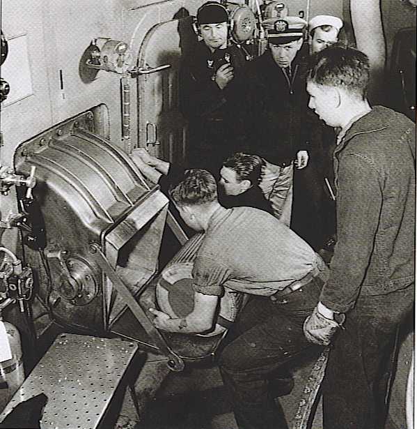
Naval Guns are usually classified by Caliber (diameter of the bore), Calibers (length of the barrel described in multiples of the diameter of the bore) and a Model or Reference designation. Some nations include a modification designation to indicate a change from the original design.
For example, the description: USN 16"/50 Mark 7 Mod 0 means that the gun was developed by the Navy of the United States of America, has a bore 16 inches (40.64 cm) in diameter, a bore length of 16 x 50 inches = 800 inches (20.320 m) and is the seventh version of the 16 inch gun and has no modifications to the original Mark 7 design.
The way barrel length is measured may differ between nations and sometimes gun types. Please see Barrel Length / Bore Length below. Generally speaking, the longer the barrel, the more powerful is the gun.
In the latter half of the 19th century, British cannon designs made a gradual transition from muzzle loading rifles (MLR) to breach loading rifles (BLR, later shortened to just BL). Any breech loader of that period which could fire faster than about two rounds per minute was known as a "quick fire" (QF) cannon, whether it used bag ammunition or cartridge ammunition. However, by the early part of the twentieth century, the BL designation was given only to bag guns while the QF designation was used only for cartridge guns. This separation into BL and QF categories was carried into the designation system, with BL and QF guns of the same caliber being enumerated into different numeric series. Except in gun lists, QF guns were not usually further subdivided into separate and fixed ammunition types. Gun designations during this time were per the diameter of the bore in inches or, for smaller guns, by the nominal weight of the projectile in pounds. A few guns, mainly those developed abroad, were designated by the bore size in millimeters, such as the Bofors 40 mm and the Oerlikon 20 mm. The bore size was followed by the BL or QF designation and then a Mark number using Latin numbers, sometimes followed with one or more asterisks or stars which indicated minor modifications to the original design. For example, the designation 4-in QF Mark XVI* meant a cartridge gun firing a 4 inch (10.2 cm) projectile, with the design being the sixteenth gun in the 4-inch QF series and having had one minor modification to the original design. One exception to this system was the Bofors 40 mm which was designated as Ordnance, Quick Firing (usually abbreviated as OQF) 40 mm Mark (whatever). For example, OQF 40 mm Mark IX was the designation of the Bofors gun used in the Mark V mounting.
Official documents generally follow the nomenclature sequence described above. However, gun breeches were usually engraved in slightly different fashion, with the BL or QF designation being first and then the bore size and mark number following along with a Wire or Steel designation denoting the construction method (see Wire-Wound and Built-up below). In addition, official documents for gun calibers that never had QF versions almost invariably omit the BL designation. For example, the famous 15-in Mark I is seldom shown with a BL designation in RN documentation as all 15 inch (38.1 cm) guns were bag guns.
Many, but not all, larger-caliber weapons designed for the British Army were given mark numbers in the same series as naval guns of that caliber, a practice which occasionally leaves a "hole" in the naval mark number series. I do not usually include a data page for such Army-only weapons, but instead put a "Nomenclature Note" on an appropriate datapage to account for these "missing" mark numbers.
For guns with fractional inch bores, the British practice in official documents was to place the decimal point directly under the inch symbol followed by the tenth inch value, a combination not readily reproducible with modern type fonts. Roughly, this would appear as 4."5 for a 4.5" (11.4 cm) gun. For clarity, I show all such designations as 4.5" (11.4 cm).
Naval mountings had a separate designation, usually incorporating the type of mounting into the designation, and enumerated by the gun caliber. For example, the mounting designation 4.7-in CP Mark XIV meant that the mounting was for 4.7-inch (12 cm) guns, was a Center Pivot type (see below), and was the fourteenth mounting in the CP series used for 4.7-inch (12 cm) guns. Similar to guns, asterisks were used to show modifications to the original design, with each additional asterisk identifying a separate modification. For example, 4.7-in CP Mark XIV** would mean the 4.7-in CP XIV mounting with two small modifications to the original design.
A few smaller mountings were designated by their total weight. For example, the 12-pdr 18-cwt was a designation given to a mounting for a 3-inch (7.62 cm) gun firing a 12-pound (5.4 kg) projectile and the gun and mounting together weighed 18-hundredweight or about 2,016 lbs. (914 kg).
Up until shortly after the end of World War II, British weapons were almost always known by their gun designation and not by the designation of the mountings in which they were used. For example, the designation of the 15-in Mark I was for the gun itself, not for its mounting. However, in 1950 the British naval weapon nomenclature system was changed such that weapons were now known by the designation of the mounting that they were used in and not by the designation of the gun itself. Also at this same time, Roman numerals were dropped in favor of Arabic numerals.
Some confusion was created under this new designation system as many older weapons were redesignated per the new system, even though the weapons and mountings themselves did not change. For example, the weapons used on the Daring class destroyers of the late 1940s were 4.5-in Mark V guns and these were used in 4.5-in Mark VI twin mountings. Under the old nomenclature system, these weapons were referred to as being the 4.5-in Mark V, in other words, by the designation of the gun itself. Under the new system, the guns and mountings together were now referred to as being the 4.5-in Mark 6, which had previously been just the mounting designation. In an effort to reduce confusion, both the original and subsequent designations are given on my data pages for these redesignated weapons, with the newer designations shown in parenthesis.
Under this new nomenclature system, modifications were also now given Arabic numerals rather than asterisks, although asterisks were brought forward for those guns having had additional modifications after being redesignated. For example, the 4.5-in Mark IV guns and 4.5-in Mark V mountings taken from scrapped "C" class destroyers and then modified and reused on the Tribal class frigates (Type 81) built in the 1950s were now designated as 4.5-in Mark 5* Mod 2. This designation meant that these mountings had been modified once prior to the change to Arabic numbers and then modified twice more after the change.
Weapons designed post-war were designated with an N (apparently for "Navy") such as the 6-in QF N5 guns used on the Tiger class cruisers in Mark 26 twin mountings.
After Britain adopted the metric system in 1965, naval guns and mountings were reclassified in metric units, although English units are still commonly used for many weapons even to the present day.
Note that none of these designation systems include barrel length (calibers) in the designation. For purposes of clarity, I have included barrel length for all gun designations on my British data pages, but strictly speaking, it is incorrect to do so.
Guns are identified by the bore diameter in millimeters or centimeters, the length in calibers of the bore and the year design was started. For example, the designation 380 mm/45 Mle 1935 (Mle = Modèle or "Model") meant a gun whose design was started in 1935, fired a 38 cm (14.96-inch) projectile and whose bore length was 38 x 45 cm long - 17.100 m (673 inches). Gun caliber was usually designated in millimeters except for two periods between about 1880 and 1890 and again between 1903 and 1922 when centimeters were used. Mountings were designated with the Model Year, for example, M1932 for a design started in 1932.
Some foreign-built weapons were in French service for a time following both World War I and World War II and used the designations assigned by those countries, but most have been produced by France and follow the above designation system. Recently, France adopted the OTO-Melara 76 mm SR gun for the joint French/Italian Horizon and FREMM frigate projects.
The methodology of German Naval Gun designations changed three times in the first half of the 20th century. In the period before and during World War I, German guns were designated by their bore diameter in centimeters, SK meaning naval cannon, and their nominal overall length in calibers. So, for example, the designation 30.5 cm SK L/50 meant a naval gun firing 30.5 cm (12.008-inch) projectiles with a barrel whose overall length was 30.5 x 50 cm long - 1525.0 cm (600.4 inches). The second method was for guns designed in the period between 1920 and 1940 where the length figure was dropped in favor of the Construction Year (Model Year). For example, under this nomenclature system the guns carried by the Bismarck were designated as 38 cm SK C/34. This designation meant that these were naval guns firing 38 cm (14.96-inch) projectiles whose design was begun in 1934. The third method was adopted in 1940 and under this system guns were designated by their bore in centimeters, KM meaning naval cannon and the Construction Year. For example, the designation 10.5 cm KM44 was for a 10.5 cm (4.1-inch) naval gun designed in 1944.
Note that neither of these last two systems included barrel length (calibers) in the designation. For purposes of clarity, I have included barrel length for all gun designations on my German weapons data pages, but strictly speaking, it is incorrect to do so for weapons designed after 1918.
Gun Mountings were designated with the type of mounting and the Construction Year. For example, the designation Drh Tr C/25 was for a turret mounting whose design was started in 1925.
Many postwar guns are foreign designs and are commonly known by the designation given by the producing nation.
Prior to the 1920s, most large caliber guns and many smaller caliber guns were imported from Britain. For that reason, most of these guns were designed and designated in inch units. Guns developed in Italy after that time were identified by their bore in millimeters, the length in calibers of the bore and the model year that the design was started either on the gun itself or on the mounting. For example, 135 mm/45 Modello 1938 was the designation given to the guns used on the "Capitani Romani" class small cruisers and these were used in Modello 1938 turrets. Often the manufacturer's name was also included as part of the designation. Mountings designed by the Italian Navy rather than by a manufacturer were given an RM designation, which stood for Regia Marina (Royal Navy).
Some USA weapons were in Italian service following World War II and used USN designations, but most post-war guns have been produced by Italian armament firms and generally follow the above designation system.
It should be noted that many Italian-produced naval guns even to the present day have been to English measurement units, not metric. For example, the main guns on the Littorio class battleships had a bore of 381 mm (15.00 inches), not 380 mm (14.96 inches) as did their French and German contemporaries. Likewise, the modern-day 76 mm Compact has an actual bore of 76.2 mm (3.00 inches).
The formal gun designation dating from the beginnings of the Imperial Japanese Navy was made up of the barrel or bore length in calibers (kôkei), a type or year type (shiki or nen shiki) which was based upon the original design date of the breech mechanism, the bore diameter and finally the suffix hô (gun). For example, the designation 40 kôkei 11 nen shiki 14 cm hô (40 caliber 11 Year Type 14 cm gun) would mean a 14 cm/40 (5.5 inch) gun whose breech design was initiated in the 11th year of the Taishô regnal era (1922 A.D.). Imported weapons had an additional designation to indicate the manufacturer.
Following the methodology of their British mentors, bore length was measured starting from the top of the mushroom head (vent axial) of the breech block for bag guns and starting from the inner breech face for cartridge guns. For a few guns, the bore length designation was actually the overall length of the barrel rather than the bore length. Unlike the British, the Japanese did not separate guns of the same caliber into bag and cartridge types.
Prior to 5 October 1917, the bore diameter was measured in English units. Guns with fractional inch bores followed British practice and were designated such as 4 in 7 (4.7 inch - 12 cm) and 5 in 5 (5.5 inch - 14 cm). For clarity, I list these as decimal values, in these instances as 4.7" (12 cm) and 5.5" (14 cm). On 5 October 1917, the Japanese Navy converted to the metric system and most naval guns were then redesignated with the bore diameter rounded up or down to a whole centimeter number, but not necessarily to the nearest value. For example, 3.0-inch guns were designated as 8 cm rather than 7.62 cm and 16.1-inch guns, originally designated in 1917 as 41 cm, were redesignated in 1922 as 40 cm. However, 5.0-inch guns were designated "correctly" as 12.7 cm rather than "incorrectly" as 13 cm. This may be a good place to note that anyone seeking consistency in Japanese ordnance designations is doomed to disappointment.
The shiki and nen shiki designations (Type and Year Type, which can be considered as being somewhat analogous to a Model Year) are quite complicated. On 25 December 1908, which was the 41st year of the Meiji regnal era, all guns in service in the Imperial Navy were redesignated. Weapons that had been manufactured by the Japanese were designated as 41 shiki hô (41 Type gun or Model 1908) even though most of them had been designed and produced prior to 1906. Guns developed after this time were assigned Year Types based upon when the design of the breech mechanism was begun. Two different calendar systems were used to define the Year Type. Between 1908 and 1927, the Year Type was based upon the year of the current regnal era, followed by the suffix nen (year), such as 11 nen shiki (11 Year Type or Model 1922). Those guns produced between 1927 and 1939 were assigned Year Types using the last two digits of the Imperial Calendar year, which dated from the start of the reign of Emperor Jimmu in 660 B.C., with 1927 A.D. being Imperial Calendar Year 2587. Guns in this series omitted the nen (year) designation, and were shown such as 98 shiki (Type 98 or Model 1938). Finally, under the Imperial Calendar system, weapons designed between 2600 and 2605 (1940-45) were designated by using just the last digit of the Imperial Calendar year such as 5 shiki (Type 5 or Model 1945).
The dates in these Type and Year Type designations should be used with caution, as they are not directly equivalent to a Model Year and in fact usually only reflect the date of the first gun design in the series. There are examples of guns with the same Year Type designation having been designed many years apart, especially in the 11 nen shiki (11 Year Type) series. These designations should be looked at as being more equivalent to a "class of weapon" designation rather than as being an actual design date.
It should also be noted that these Japanese Year Type designations do not translate well into English. For example, although a literal translation of 11 nen shiki hô would be 11 Year Type Gun, this sounds "wrong" to English-speakers. For that reason, most English translations of this designation would show it as either 11th Year Type or as Type 11. Neither of these are literally correct translations, but sound "better" to English-speakers. On my data pages, Japanese designations are shown such as 11th Year Type for regnal-era calendar guns and such as Type 94 for Imperial Calendar-era weapons. As noted above, neither of these are literally correct, but I believe them to be more easily understandable by English speakers and better indicate the era in which they were designed.
On my data pages, the Year Type in A.D. is always noted and all known designations that a weapon had during its design and service life are listed.
Ammunition casing head stamps seem to have continued to use the regnal calendar. For example, a head-stamp of S 10/17 would mean that it was made during the Showa regnal era in October 1942.
The gun barrels themselves were designated with a numbering system somewhat similar to the USN Mark and Mod system (see below). The earliest barrel design was designated as Roman numeral I, later minor modifications were given numeric subscripts such as I2, I3, etc. Major changes to the design were given higher Roman numerals, such as II, III, etc. On my datapages, these barrel designations are usually shown such as Model Type I2.
It should be noted that the Japanese Model number system became chaotic towards the end of World War II. New weapons were assigned Year Type designations that had no relationship to the actual date of design, with some apparently chosen simply to fill in missing years in the series. As John Campbell put it, "such are the pitfalls of Japanese ordnance [nomenclature]."
As examples of Japanese designations for naval guns:
- Japanese-built versions of the Armstrong Elswick 8"/45 (20.32 cm) guns were redesignated on 25 December 1908 as 45 kôkei 41 shiki 8 in hô - 45 caliber 41 Type 8-inch gun or 8"/45 (20.32 cm) Model 1908, although the first guns were produced at the Kure Navy Yard in 1902. These guns were redesignated on 5 October 1917 as 45 kôkei 41 shiki 20 cm hô - 45 caliber 41 Type 20 cm (7.87-inch) gun, although their bore remained unchanged at 8.0-inch (20.32 cm).
- Under the regnal era and english measurement systems, the Japanese-built 14-inch guns carried by the Kongô class were originally designated as 45 kôkei 41 shiki 14 in hô - 45 caliber 41 Type 14-inch gun or 14"/45 (35.56 cm) Model 1908, although the original design by Vickers dated from 1910 and no guns were produced in Japan before at least 1912. They were then formally redesignated in metric measurment units on 5 October 1917 as 45 kôkei 41 shiki 36 cm hô - 45 caliber 41 Type 36 cm guns - even though the bore size remained unchanged at 35.56 cm (14.0-inch).
- Under the Imperial Calendar system, the AAA guns carried by the Agano class cruisers were designated as 60 kôkei 98 shiki 8 cm hô - 60 caliber 98 Type 8 cm gun or 8 cm/60 Type 98. However, these guns actually had a bore size of 7.62 cm (3.0-inch).
- The British 2-pdr gun made by Vickers and exported to Japan in the 1930s was designated as 62 kôkei 91 nen shiki 40 mm "BI" - 62 caliber 91 Year Type 40 mm "BI", where "BI" (also translated as "HI") was the designation meaning Vickers. This designation is notable for using the overall barrel length rather than the more common Japanese method of being per the bore length, which was 39 calibers, identical to other Vickers 2-pdr. guns.
Postwar guns are primarily foreign designs and are commonly known by the designation given by the producing nation.
Weapon systems other than naval guns were designated as to when they entered service. For example, the famous Zero fighter plane of World War II derived its name from its designation, Type 0 carrier-based fighter, as its service introduction was in the Imperial Calendar year 2600 (1940).
Prior to 1917, designations included the bore size, overall barrel length and the Obrazets - Pattern (Model) Year. Guns were designated either by their caliber in inches if it was a whole number or in millimeters for all others. The Pattern Year was the date that the weapon was accepted into service. After 1917, a project number was added and all gun calibers were then designated only in millimeters. As an example of the post-1917 designation system is 130 mm/50 B13 Pattern 1936, which meant that this was a weapon firing 130 mm (5.1-inch) projectiles, had a barrel 50 calibers long, was designed at the "Bol'shevik" plant as Project 13 and which entered service in 1936.
Up until just after World War II, each caliber of USN guns was identified by its length in calibers, a mark number and a modification number, the original modification designation being Mod 0. For example, 16"/50 Mark 7 Mod 0 meant a gun firing 16-inch (40.64 cm) projectiles with a barrel 16 x 50 = 800 inches (20.320 m) long, was the seventh gun in the 16-inch (40.64 cm) series and was built to the original design with no modifications. A few smaller guns built or purchased mainly in the latter part of the 19th century were known by the weight of their projectiles; the 1-pounder, 3-pounder and 6-pounder series.
When a USN ordnance item is approved for testing, it is assigned a Mark number. It retains this Mark number whether it is finally approved for service use or if it is rejected. Modifications to the Mark design are treated in a similar manner. Roman numerals were originally used for Mark and Mod designations (such as Mk I M II) until June 1925 when Arabic numerals were adopted (such as Mk 1 Mod 2).
Gun Mod numbers generally indicated changes to the original design for new guns or a change made to a finished gun. For example, a change in the rifling pattern from the original design might be designated as Mod 1 and new guns built with this rifling would be so designated. Guns more heavily modified would be given new Mark numbers, such as the 14-inch (35.56 cm) Mark 4 guns that were rebuilt during the 1930s and then redesignated as Mark 11 guns.
Identification markings on the breech had the above designations along with the serial number and the weight of the gun barrel in US pounds. Guns that had their original liner replaced had an L suffix added after the serial number and this was also carried over into the Gun List. The second time the liner was replaced the suffix was changed to L2. The liner number was then incremented each additional time that the liner was replaced.
One further serial number item to note: If a gun suffered a catastrophic failure such that it was uneconomical to repair, a new gun would be built to replace it. Rather than giving this new gun a new serial number, it would instead use the serial number of the destroyed gun with the suffix "A" added to indicate that it was a replacement for that gun. For example, if the destroyed gun was serial number 49, then the replacement gun would be serial number 49A.
Mountings originally had a similar designation, being of the form 12" Mark 8 Mod 0 for a mounting using a 12-inch (30.5 cm) weapon. By 1930, the Mark number mounting designation had been dropped for weapons larger than 5 inches (12.7 cm) and new mountings were then known by the ship class they were used on. For example, the mountings for the 16"/50 (40.64 cm) Mark 7 guns used on the Iowa class battleships did not have a Mark number and were instead designated as 16-inch, Three Gun Turret, BB-61 class. Mountings for 5 inch and smaller guns continued to have Mark numbers assigned to them.
Similar to Britain, shortly after World War II the USN designation system was changed from being based upon the gun classification to being based upon the mounting classification. So, a modern designation such as 5"/54 Mark 45 is really the designation of the gun mount, not the weapon itself. A few older weapons such as the 5"/54 Mark 16 are occasionally seen in publications per their Mark 39 mounting designation, but this is rare and seems to be an effort to put all 5"/54 guns into the same designation series. Furthermore, starting with the 5"/54 Mark 42, almost all naval guns are now classified into a single Mark series, regardless of their caliber. For example, modern guns such as the 5" Mark 45, the 76 mm Mark 75 and the 57 mm Mark 110 are all in the same numeric Mark series.
For aircraft ordnance of the World War II era, the Army and Navy standardized on many items and these were given the letters "AN" (Army - Navy) before their designations, such as AN-Mk 33 (originally developed by the Navy) or AN-M63A2 (originally developed by the Army).
AA - Anti-Aircraft.
AAA - Anti-Aircraft Artillery. Refers to larger caliber guns used as anti-aircraft weapons, usually any AA gun larger than about 2.5 in (6.4 cm).
AA/Su - Anti-aircraft/Surface. British designation used to denote dual-purpose weapons or fire control systems. This replaced the previous "HA/LA" designation in 1947.
akan - automatkanon. Swedish (Bofors) for "Automatic Cannon."
ATB - Anti-Torpedo Boat gun. Weapons employed to repel torpedo boats. Usually the secondary or tertiary batteries mounted on pre-dreadnoughts and dreadnoughts of the 1880s to 1920s. The caliber of these guns grew rapidly from the 1-pdrs. of the 1880s to the 5.9in (15.0 cm) and 6-in (15.2 cm) guns of the World War I era.
BL - British designation meaning Breech Loading cannon. In the 1800s the the British used the designation BLR where the "R" stood for Rifle, but after about 1890 the "R" was dropped from new gun designations. By the early part of the twentieth century, BL had become to be used only for bag ammunition guns.
BM - Breech Mechanism. See "Breech Mechanism" section below.
BMG - Browning Machine Gun. These were recoil-operated machine guns of various calibers originally designed by the USA inventor John Moses Browning (1855 - 1926), the most famous being the "fifty-caliber." The modern version is the 0.50" (12.7 mm) BMG M2HB, with M2HB meaning Mark 2 Heavy Barrel. The M2 designation is why this weapon is often known as the Ma Deuce.
Bolt - The mechanism that positions the cartridge in breechloading guns, closes the breech, and ejects the spent cartridge case.
Bolt Open or Open Bolt - Refers to automatic or semi-automatic weapons that are designed such that the gun bolt is normally held to the rear of the weapon, leaving the breech open. Only after the trigger is activated is the next round pushed into the firing chamber and the breech closed. This design reduces the chances of an accidental "cook off" as no bullet is in the firing chamber until after the trigger is activated.
Bolt Closed or Closed Bolt - Refers to weapons that are designed to hold a bullet in the firing chamber with the bolt closed prior to activating the trigger.
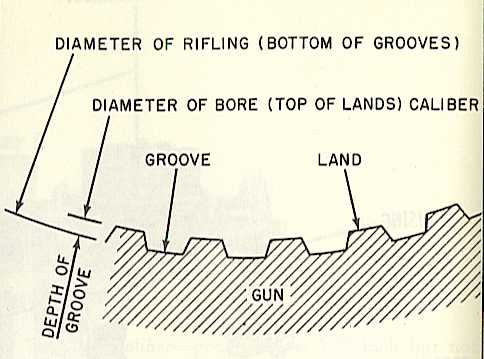
Bore - Inner Diameter (ID) of the barrel. This is measured from land surface to diametrically opposed land surface. For example, the USN 16"/50 (40.64 cm) guns used on the Iowa class battleships had a new gun land to land diameter of 16.00 inches (40.64 cm) while the diameter as measured from the bottom of the groove to the opposite bottom of the groove was 16.30 inches (41.40 cm). "Bore" is also used as a shorthand reference for "Bore Length" - see "Barrel Length / Bore Length" below.
Bore, Squeeze - The bore near the muzzle is slightly reduced in diameter in order to better center the projectile before it leaves the gun. This reduction also flattens out the driving band, thus giving the projectile a better aerodynamic shape. For a related design, see "Probertised" below.
Breech - The rear of the gun. In most 20th century guns, where the shell goes in, hence the name "Breech Loader." See "Breech Mechanisms" below.
Caliber and Calibers - "Caliber" refers to the bore diameter of the gun barrel or to the diameter of the projectiles fired. "Calibers" refers to the length of the gun barrel in multiples of the projectile diameter.
Chamber - Part of the gun in which the propellant charge is placed. In a bag gun, that space between the obturator or breechblock and the forcing cone. In fixed or semi-fixed ammunition, the space occupied by the cartridge case.
Chamber, Fluted - Small longitudinal channels cut in the chamber walls, used in many semi- and fully-automatic weapons. When the cartridge is fired, these channels allow a small portion of the propellant gases to get between the cartridge case and the chamber walls, preventing the cartridge case from "sticking" to the chamber walls, thus making it easier to extract.
Chamber Size - Space available for gas expansion when the projectile is seated in position; measured from the face of the closed breech block, around the base of the projectile, to the rear of the rotating band (or obturator). In fixed ammunition, it is the volume of the cartridge case behind the projectile.
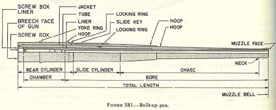
Chase - The part of the gun barrel forward of the slide cylinder and behind the muzzle (or neck for guns with muzzle bells). This portion of the barrel is usually tapered as the barrel pressure lessens towards the muzzle.
Chrome Plating - In the 1930s, the USN started to chrome plate the bores of most guns to a depth of 0.0005 inches (0.013 mm). This was "hard chrome," which is not the kind that you find on your father's Oldsmobile. This plating increased barrel life by as much as 25%. The plating generally extended over the length of the rifling and shot seating. Chrome plating has also been found to reduce copper deposits.
CIGS - Close In Gun System. A weapon system designed to combat small boats at short ranges - the "Boghammer" threat.
CIWS - Close In Weapons System. A weapon system designed to combat anti-ship missiles or aircraft at short ranges.
Cup Obturation - I cannot possibly improve upon Mr. Ruffell's description. Part of "The Gun" by Mr. Ruffell.
cwt - Hundredweight. British unit of measurement that was used to designate smaller weapons by the weight of the gun and mounting. One hundredweight is 112 pounds (50.8024 kg).
De Bange Obturator System - See "Obturator" below.
DEF - Direct Electric Firing, usually abbreviated as "E." British gun prefix designation meaning that the gun was fired by electric arcing.
DP - Dual Purpose. These guns are intended to be used against both surface and aircraft targets. Maximum elevation of these guns is usually greater than 50 degrees.
EMF - Electro Mechanical Firing, usually abbreviated as "F." British gun prefix designation meaning that the gun was fired by electromotive force, i.e., a solenoid activating a striker pin.
EFC or ESR - A means of estimating the remaining accuracy life of a weapon. Accuracy life for a gun or liner is usually expressed as "EFC" meaning Equivalent Full Charges or as "ESR" for Equivalent Service Rounds. On my webpages, this is the number specified. A gun or liner has reached the end of its accuracy life when the projectiles and propellant charges assigned for its use give range patterns that exceed an arbitrarily adopted size, generally something like 10 percent larger than those with a new barrel. For large caliber guns, life is roughly the same as the number of AP shells that can be fired with full charges before the barrel needs to be replaced or relined. Compared to rounds fired with full charges, Practice Rounds and shells fired with reduced charges generally cause less wear, while proof charges and super charges cause more wear. The amount of wear immediately forward of the origin of the rifling is the most important value used in determining the remaining life. The three main causes of bore erosion are thermal stress, mechanical wear and chemical erosion. The greatest source of wear is from the propellant gases, which corrode the rifling via heat and chemical action.
FER - Fatigue Equivalent Rounds. The mechanical fatigue life of a gun barrel or liner expressed as the number of mechanical cycles the gun barrel or liner can withstand before needing to be replaced. This has replaced EFC/ESR for some modern weapons.
Firing Lock or Primer Chamber - A feature of the breech mechanism used for bag guns, this is a small enclosure into which the igniter or primer is inserted. See "Primer vent or vent axial" below.
FLAK - FliegerAbwehrKanone. German designation for AA weapons (FLAK guns). Literally means "Flier Defense Cannon." During World War I, this term was used by Allied airmen to describe the shell bursts from such weapons, which has become the current accepted meaning of the term.
Forcing Cone or Seat - The forward end of the gun chamber where it necks down to the start of the rifled portion of the barrel. This guides the projectile as it is being rammed.
GAU - US Military designation for airborne guns and gun systems.
Grooves - A rifled gun is so called on account of the spiral grooves which are cut into the surface of the bore and into which the soft metal projectile driving bands are forced during its travel down the bore. See "Rifling" and "Twist" below.
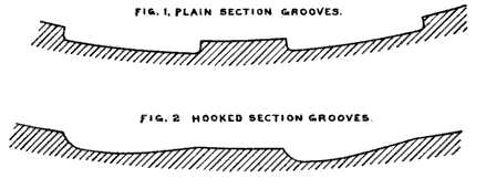
Grooves, Plain-Section - A rifling pattern where the bottom of each groove is concentric with with the bore and the sides of which terminate in a small radius.
Grooves, Hook-Section - A rifling pattern which has a "driving" side which exerts a high pressure on the projectile driving band while the other side of the groove has a gentler slope which exerts little pressure on the driving band. In a gun with RH twist, the driving side is on the right hand side.
GWS - Gun Weapon System.
HA - High Angle. British designation used to denote DP or AAA guns or directors. Meant that the gun could be elevated past about 50 degrees or that the director was intended for AA use. Replaced by "AA" in 1947.
HA/LA - High Angle/Low Angle. British designation of World War II equivalent to DP. Meant that a gun or director was intended for use against both surface and aircraft targets. This designation was replaced by AA/Su (anti-aircraft/surface) in 1947.
Hornrings - Rings shrunk onto German heavy guns to which the piston rods of the recoil and run-out cylinders were attached.
IV - Initial Velocity. Velocity of the projectile upon leaving the barrel of the gun. Equivalent to "Muzzle Velocity."
Key - Metal bar attached to the top of a gun barrel to prevent rotation. See "Slide Cylinder" below.
KM - Kanone Marine. German for "Naval Cannon." Usually followed by the model year. For example, KM42 meant a naval gun designed in 1942. This designation system was used for some guns designed between 1940 and 1945.
LA - Low Angle. British designation used to denote SP guns or directors. Means that they are intended for use solely against surface targets. Replaced by "Su" for surface in 1947.
Lands - The bore surface between rifling grooves inside the gun barrel. See "Rifling," below.
Life - See "EFC or ESR," above.
MG - Machine Gun.
MK or Mk - Abbreviation for "Mark."
MLR - British designation meaning Muzzle Loading Rifle.
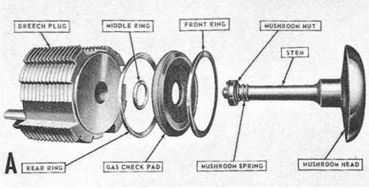
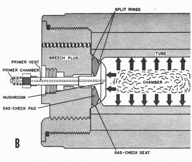
Mushroom Head - A component of Welin breech-blocks, this is the forward part of the breech-block located between the chamber and the obturator. When the gun fires, the Mushroom Head squeezes the gas check pad and seals the breech, preventing propellant gases from escaping.Muzzle - The fore or "Business End" of the gun. Where the shell comes out.
Muzzle Bell or Swell - Many guns have a barrel thickening at the muzzle. This is meant to strengthen the gun barrel at the muzzle and so prevent the guns from splitting. This feature is also known as the muzzle "tulip", "lilly" or "flare." Modern weapons use higher quality steel and so lack a bell, or instead have lugs, which are utilized when the liner is replaced (the lugs serve to anchor the tool used for pulling the liner out).
Muzzle Brake - A device on the muzzle which diverts part of the propellant gases to the sides or rear in order to reduce the recoil force.
Muzzle Droop - As in any unsupported structure, a gun barrel bends due to the action of gravity. The vertical distance that the muzzle end of a gunbarrel moves from its "ideal" position is called droop. Gun barrels are usually orientated in their mountings in the direction that produces the least amount of droop.
MV - Muzzle Velocity. The velocity of the projectile as it leaves the gun barrel. Equivalent to "Initial Velocity."
Nendo Shiki - Japanese for "Year Type." See "Japanese Designations," above.
Neck - The narrow portion of the barrel directly behind the muzzle bell - see "Muzzle Bell" above.
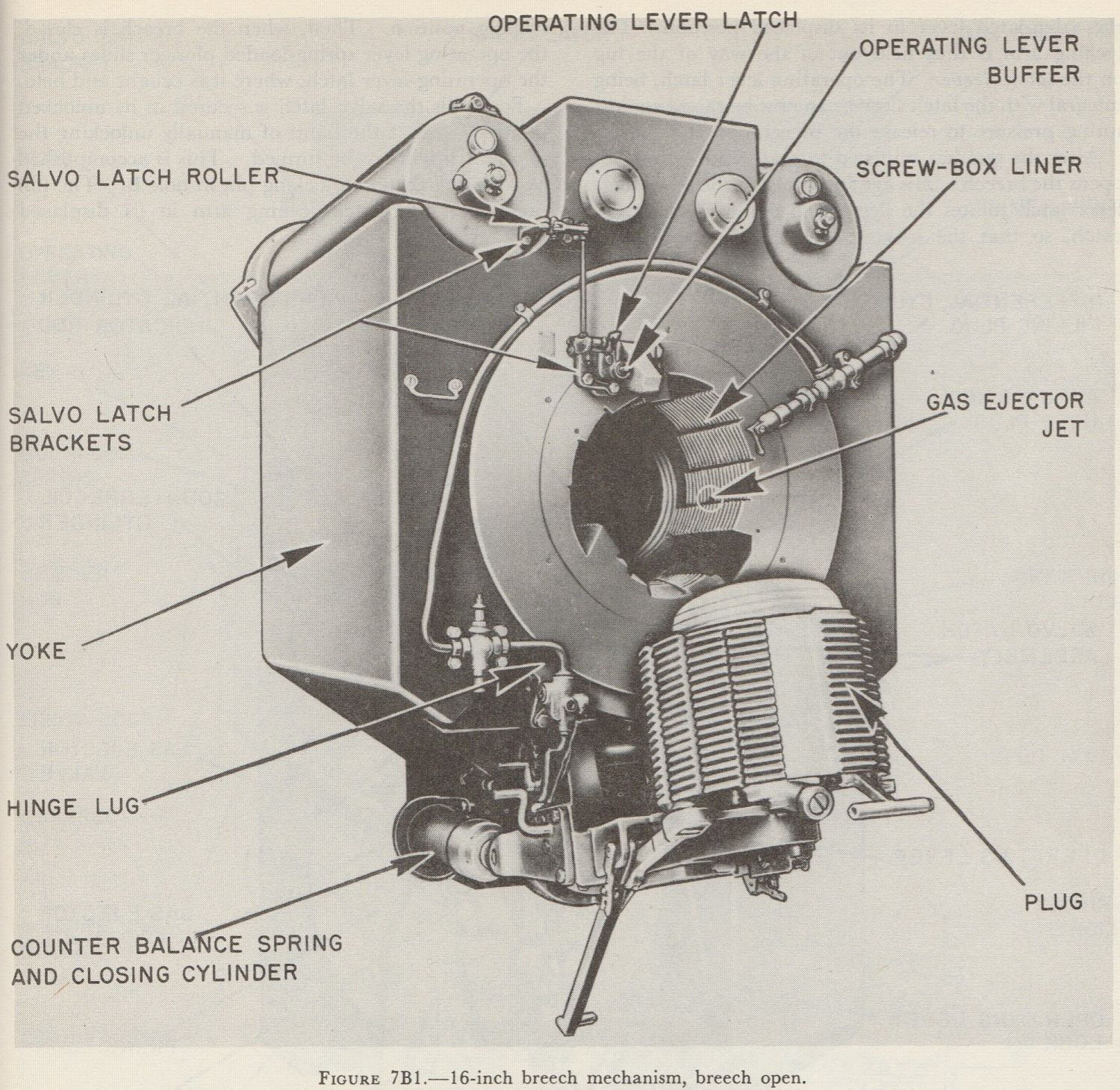
Obturator - For breech loading guns, this is a device for making the breech gas-tight, preventing any escape of propellant gas while the breech is closed. For bag guns using Welin breech blocks, the De Bange obturator system (named after Colonel Charles Ragon de Bange of the French Army, who invented it in 1872) was commonly used. The De Bange obturator system consists of a doughnut-shaped washer pad, also known as a "gas check pad," that is located between the mushroom head and the screw breech. See the breech illustrations for details. When the breech is closed, rotating the screw squeezes the pad against a conical section of the gun barrel. When the gun is fired, the mushroom head is driven back against the pad which forces it tighter into the conical seating and thus seals the barrel. For guns using cartridge ammunition, the cartridge case itself becomes part of the obturator system. Generally speaking, both the cartridge case lip and cartridge case mouth are used to seal the barrel. The cartridge case lip is forced tightly against the breech when closed while the chamber of the gun is designed such that the expansion of the mouth of the cartridge case when the gun fires helps to seal the barrel. Also see "Obturator" under Projectile Definitions.
Pdr. - A way designating weapons in terms of the weight of the projectile they fired. For example, the British 2-pdr. AA gun fired a shell weighing about two pounds (0.9 kg). For reasons that can only be described as traditional, the British, alone of all modern nations, clung to this method of designation well into the twentieth century, long after other nations had switched to designating weapons by their bore diameter.
Pom-pom - This term originated with the British 1-pdr. used during the Boer War and was later applied to the 2-pdrs. of World War I and II. Reportedly, this was the sound made by large automatic guns when firing.
Primer Channel - See "Firing Lock" above.
Primer Vent or Vent Axial - A feature of the breech mechanism used for bag guns, this is a hollow tube running from the firing lock or primer chamber through the stem to the front of the mushroom head. When the igniter or primer is fired, it generates a flame which travels through this tube into the propellant charges. See the above obturator illustration.
Probertised - A gun barrel where the rifling grooves near the muzzle gradually disappear until the last section of the barrel becomes smoothbored. When a projectile travels through this section, its driving bands get flattened against the shell body, giving the projectile a smoother shape and thus improving its aerodynamics. Named after the inventor, British Colonel G.O.C. Probert of the Woolwich Arsenal.
QF - British designation meaning Quick Firing cannon. In the late 19th and early 20th centuries, this term was used to define any gun that could be fired several times per minute whether it used bag or cartridge ammunition. By the 1920s this designation was given only to guns that used metallic cartridge cases.
QFC - Quick Firing, Converted. Early British Bag guns modified to use cartridge cases.
Receiver - The main portion of the weapon, to which the barrel and operating mechanism are attached.
Rib-Rifling - Rifling pattern where the grooves are very wide and the lands are very narrow. Lands are known as Ribs for this kind of rifling.
Rifling - The bores of most gun barrels have grooves milled into them in a spiral pattern. These grooves engage the Driving Bands on the projectiles and thus impart a spin to them as they leave the barrel. Spinning the projectiles makes them more stable in flight which greatly increases their accuracy and range. It also makes them more likely to land nose first, which is very important for an armor-piercing shell. The way the grooves are milled varies greatly. Some manufacturers prefer a uniform pattern, others prefer grooves that vary in depth and width as they progress through the weapon. See "Twist" below.
RF - Rapid Fire. USN term equivalent to QF during the end of the 19th century and first half of the twentieth century. At the end of World War II, this term was used to describe large caliber guns with automatic shell-handling equipment such as those carried by the USS Des Moines (CA-134) class heavy cruisers.
ROF - Rate of Fire. Usually shown in terms of RPM - Rounds per Minute. ROF may be affected both positively and negatively by many different elements, too numerous to list here. ROF figures given on my data pages for manually-operated guns represent nominal values and should not be interpreted as being literally correct under all circumstances. ROF figures on my data pages for automatic weapons are usually the cyclic values, with practical values given where possible. It should be noted that an air-cooled automatic or semi-automatic gun can be fired continuously at its maximum cyclic rate for only a short period, otherwise its barrel will start to soften or melt. Automatic guns using a water jacket, especially those with a recirculation method including a radiator, may fire continuously at their maximum cyclic rate for much longer periods, as the cooling water helps to keep the barrel below the melting point.
rpgpm - Rounds per gun per minute. The rate of fire of each gun in a multiple gun mounting.
RPM - Rounds per Minute. On my data pages for multiple gun mountings, this is always listed in terms of rpgpm.
SAK - Skepps Automat kanon. Swedish (Bofors) for "Naval Automatic Cannon."
Salvo Latch - Safety device that locks the breech mechanism and prevents the breech from opening until after the gun has fired.
Screw box liner - The barrel sectional casting to which a screw breech block screws into when closing. Known as the "breech bush" in British weapons.
Sear - Holds the firing pin in a cocked position against the compression of a spring until the trigger is activated, which allows the spring to drive the firing pin into the primer.
Separate Loading - See "Bag Guns" below.
SF - Slow Firing. This may not have been an official designation, but instead may have been a way of differentiating those guns that were not "QF" or "RF" types.
SK - Schnelladekanone or Schnellfeurkanone. German for "Fast Firing Cannon," equivalent to QF or RF. Also listed as being for "Schiffskanone" or "Ship Cannon." See "German Designations" above.
Slide - The slide is that non-recoiling part of the mounting through which or upon which the gun or the gun slide cylinder moves in recoil and counter-recoil motions. The slide moves with the gun in train and elevation. For many large caliber guns, these are one or two "rails" underneath the gun and upon which the gun in its carriage rests. When the gun fires, recoil pushes the gun in its carriage down the slide. Counter-recoil mechanisms then push the gun and carriage back up the slide and "into battery" so that the gun can be reloaded. The USN used a cylindrical side which allowed the gun barrel to be inserted or withdrawn through the gun port without needing to dismantle the gunhouse. This not only sped up the gun replacement process, but also resulted in a stronger gunhouse.
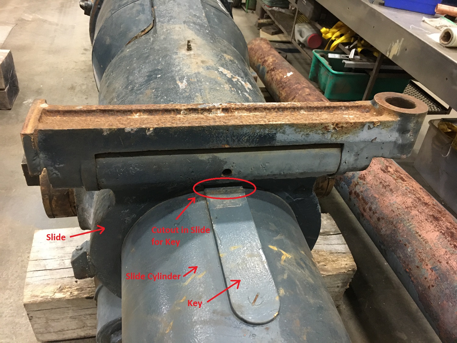
Slide cylinder - The part of the gun barrel forward of the rear cylinder which fits into the slide and moves through it during recoil. A Key is bolted on top of the barrel on the slide cylinder which interacts against the slide to prevent rotation of the gun due to the reaction of the projectile on the rifling. Prior to the introduction of this system, straps attached between the gun barrel and the carriage were used to prevent rotation.
Smoothbore - A gun barrel or gun barrel section that does not have any rifling.
SP - Single Purpose. Means that the weapon is intended for use only against surface targets. Maximum elevation of these guns is usually less than 45 degrees.
STAAG - Stabilized Tachymetric Anti-Aircraft Gun.
Su - Surface. British designation for SP guns. This replaced the previous "LA" in 1947.
Stabilized - When a mounting is referred to as "stabilized," it means that it contains some method for correcting for the deck inclination caused by the rolling and pitching of the ship. Usually, this involves more than two axis of motion (traverse, elevation) and requires gyroscopes.
Striker Gear - The firing pin and associated mechanisms used in percussion firing.
TAK - Torn Automatkanon. Swedish (Bofors) for "Turret Automatic Cannon."
Tampion or Tompion - A plug that goes into the muzzle of the gun. Keeps the sea spray out of the barrel. In the USN, pronounced "tom-kin."
Taper wound or Taper winding - British method of wire-wound gun construction in which a single length of wire is used rather than multiple lengths. Introduced following World War I. See "Wire-wound Construction" below.
TBK - Torpedoboots Kanone. German for "Torpedo Boat Cannon." Also shown as Tbts K.
Trunnion - The cylinders upon which the gun barrel pivots up and down.
Tube - Gun barrel section. See "Built-up Construction," "Monobloc Construction" and "Wire-wound Construction."
Twist - Rifling grooves make a spiral towards the gun muzzle. The length of the barrel necessary for the grooves to make one complete revolution is called "Twist." This is usually expressed in calibers but sometimes appears in measurement units (inches or meters). On my data pages, Twist is specified in calibers, with "RH 1 in 25" meaning that, when looking at the top of the barrel from the breech end of the gun, that the spiral goes in a right-hand direction and that it takes 25 calibers for the grooves to make one complete revolution. Depending upon the internal ballistics desired, the spiral may be of a uniform pattern, where the angle of inclination remains constant throughout the bore, or it may be of a parabolic pattern with the twist increasing as it nears the muzzle. The steepness of the twist is related to the length and weight of the projectiles fired. Twist is intended to make a projectile spin at a stabilizing rate as it exits the barrel. Generally speaking, a longer, heavier projectile must spin faster than a shorter, lighter projectile in order to remain stable in flight. As a rule of thumb, a projectile fired from a smaller caliber gun spins close to 100% of the rate determined by the muzzle velocity divided by the twist length. By contrast, due to slippage caused by inertia, large-caliber projectiles spin at about 90% of the rate determined by the muzzle velocity divided by the twist length. As an example of calculating spin rate, for a 16 inch (40.64 cm) gun with a uniform twist of 1 in 25, the barrel length required for the twist to make one full rotation would be 16 x 25 = 400 inches or 33.33 feet (10.16 m). Nominally, this twist would mean that a projectile with a muzzle velocity of 2,500 fps (762 mps) would be rotating as it left the muzzle at about 75 RPS or 4,500 RPM, but because of slippage it is actually rotating at about 67.5 RPS or 4,050 RPM. Because of gyroscopic and corolis effects, a shell fired from a gun with RH twist will tend to drift to the right while one fired from a gun with LH twist will drift to the left. Drift due to the corolis effect is near zero at the equator and at its maximum at the earth's poles. The amount of drift is also affected by the direction of fire. Fire control systems have input settings for the ship's latitude and the direction of fire so as to correct for these effects. Note: I have never found a naval cannon with LH twist, they all have RH twist. I have found a few small-arms that use LH twist, including the famous Colt black-powder pistols of the mid-1800s, but most small-arms use RH twist.
ubätsautomatkanon - Swedish (Bofors) for "Submarine automatic cannon."
UBK - Untersee-Boots Kanone. German for "U-boat Cannon." Also shown as "Ubts K."
Water-cooled - A weapon which uses a water-jacket around the gun barrel. These are used on machine guns and rapid-fire weapons in order to keep the barrel from softening or melting during prolonged firings. The development of higher-quality alloys in recent years has reduced or eliminated the need for water jackets on many newer weapons.
Working Pressure - The pressure generated inside the barrel by the burning propellant. This pressure is measured at the breech of the gun. Because of the pressure gradient in the barrel, the peak pressure at the base of the projectile is at a smaller value. A reasonable rule of thumb is that the pressure at the breech is between 1.16 to 1.2 times greater than the pressure seen at the base of the projectile. It should be noted that the pressure values found in reference works for older guns are not particularly accurate. Pressure was measured by the size of a copper cylinder that was crushed when the gun was fired. The size of the cylinder crushed was converted to "copper units of pressure (CUP)." Historically, the chamber pressure for U.S. Naval guns has been specified in long tons copper per square inch (tsi). To convert to true pressure, the copper tsi is multiplied by 2.688 to get pounds per square inch (psi). The copper cylinder method has been made obsolete by the invention of piezoelectric strain gauges which have made pressure measurements much more precise. Copper tubes are still used by both the US Army and Navy for tests where only peak pressure testing is required, such as for barrel proof or ammunition lot acceptance. Modern smaller caliber guns are usually rated in terms of psi (pounds per square inch) or MPa (megapascals).
Yoke - The large ring surrounding the breech end of the barrel which provides a connection between the barrel and the recoil system. Shoulders on the gun prevent movement between the barrel and the yoke. In guns designed for case ammunition, the yoke is replaced by a housing.
Autofrettage - A process in which a favorable distribution of initial or residual stress in a tube is induced, as in the manufacturing of gun barrels. Literally means "self-hooping" and the process involves expanding a partially machined barrel or liner by applying hydraulic pressure to the interior surface. The metal of the bore is the first to be stretched beyond the elastic limit. The process is continued until the metal at the outer surface just reaches its elastic limit. At this point, the increase of hydraulic pressure in the bore is halted and soon afterwards the pressure is reduced to zero. Since the metal at the bore has received a certain amount of plastic deformation, it would, if left free to do so, retain all of this "set." However, since the metal at the outer surface has received no permanent set, but only a strain within the elastic limit, it attempts to return to its original diameter. The metal between the bore and the outer surface has received some plastic deformation, decreasing outward. The final result is that the bore is forced back to a diameter somewhere between the original diameter and that which was attained under the maximum hydraulic pressure. Thus, the bore has received a certain amount of tangential tension, exactly as in the case of a built-up gun, but with the difference that the autofrettage process results in a indefinite number of layers, each infinitesimal in thickness, and having varying stresses which result in producing the maximum possible strength in the finished gun. This process allows steels with low alloy content to be used to make gun barrels. During the 1920s and 1930s, the US Navy termed this process "manufacture by radial expansion."
Bag Guns - Weapons that used powder bags rather than a cartridge case to hold the propellant. This was the most common ammunition type of the twentieth century for 6 inch (15.2 cm) and larger guns. Guns using powder bags were designated as "Separate Loading" in the USN, a reference to the normal procedure for bag guns of first ramming the projectile and then the powder bags. Smaller calibers generally use a single bag while larger calibers may have as many as six bags. See "Bag Ammunition" on the Ammunition Definitions data page for additional information.
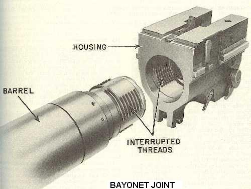
Bayonet Joint - An interrupted-thread method of attaching the gun barrel to the housing in order to make for easier barrel replacements.
Barrel Length / Bore Length - One of the more confusing items about gun designations is that the way that the length (calibers) of a gun barrel is measured differs from nation to nation. The USA measured starting from the inner breech face for both bag and cartridge guns. Austria-Hungary (Škoda), Germany and Russia measured the length of the entire barrel. Britain, France, Italy, Japan and Sweden (Bofors) measured starting from the top of the mushroom head (vent axial) of the breech block for bag guns and starting from the inner breech face for cartridge guns. These differing methods have often resulted in nomenclature errors in reference works. For example, the 38 cm SK C/34 guns on the German battleship Bismarck are often noted as being 47 calibers long. Per the German method - overall barrel length - these guns were 51.66 calibers long and per the British/USA method - measured from the inner breech face - they were 48.3 calibers long. As every German document I have seen refers to these guns as being the equivalent of either 51.66 or 52 calibers long, I am not certain why so many authors refer to these guns as being 47 calibers long. My thanks to M.J. Whitley, whose series of books on German Warships of World War II first enlightened me on how the German methods differed from those of other nations. On my webpages, "Gun Length oa" refers to the overall barrel length. "Bore length" is per each nation's specification except where noted.
Built-up Construction - Guns that are manufactured from multiple hoops (tubes) which are joined together with locking rings and overlapping sections to make longer and/or thicker sections. This was the most common process for manufacturing almost all guns until the 1920s when monobloc techniques were introduced for guns smaller than about 6 inches (15.2 cm). See "Monobloc" and "Wire-Wound" below.
Cartridge Guns - Weapons in which a metallic container, usually brass or steel, is used to hold the propellant. Most commonly used for "Quick Firing" and automatic weapons.
Hoop or Tube - A section of the gun barrel. See "Built-up Construction," "Monobloc Construction" and "Wire-wound Construction."
Housing - A forging for case guns that holds the sliding breech block mechanism and where the gun barrel attaches. For many USN guns designed for case ammunition, the housing took the place of the yoke and screw-box liner used on bag guns. This construction method allowed the elimination of the slide cylinder for some gun designs. See illustration for "Bayonet Joint" above.
Liner - A replaceable tube within the gun barrel. The useful life of a gun is measured by how much rifling remains. By having the rifling milled into a replaceable liner, the life of the gun barrel itself is increased by many times.
- Conical Liner - A liner whose outer diameter reduces from the chamber to the muzzle. The inner diameters of the tubes overlapping the liner likewise reduce from the chamber to the muzzle. This eases liner replacement as any rearward motion as the liner is extracted will create a gap between the liner and the overlapping tubes.
- Loose Liner or Loose Barrel Construction - Means that the gun was built with a small clearance between the outer diameter of the liner and the inner diameter of the next outer part. When firing, the gas pressure elastically expands the liner but otherwise the clearance remains. This method of construction makes it easy to replace the liner after removal of the locking devices. The replacement method for other types of liners is much more complicated. See "Gun Pit" in Gun Data - Part 3.
Locking Ring - A short cylindrical casting used for joining gun barrel tubes together. See "Hoop" above.
Monobloc Construction - A gun built from a single tube apart from the breech-ring and breech mechanism rather than a multi-tube built-up design. During the 1920s, when centrifugal spun castings came into being, it became possible to make cylindrical castings with a precise wall thickness and density with no cracks. The inside diameter of these spun castings could be controlled to the point where very little machining had to be done to true-up the inside diameter. The general process was to make three tubes; the gun barrel itself, the breech ring and a liner, which together made up the gun barrel. These three tubes were assembled onto each other with the breech ring making a thicker and thus stronger section at the breech end of the gun. Later designs for guns smaller than about 6 inches (15.2 cm) further simplified the manufacturing process by eliminating the separate liner. Monobloc construction makes for a straighter, stronger barrel than does built-up construction and overcomes some of the problems with having to make one solid casting with a thickening at the breech. This older style of casting had cooling problems due to the uneven wall thickness which could lead to cracks developing.
Wire-wound Construction - A method of strengthening built-up gun barrels by using long lengths of wire wrapped around an inner tube. This method of construction was used extensively by the British roughly between 1880 and 1925. Few nations other than Japan adopted this technique as it greatly complicated the manufacturing process. The wire was about 0.1 inches (2.5 mm) thick and had a rectangular cross-section or was sometimes ribbon-shaped. The wire was quite strong with tensile strengths of up to 200,000 psi (14,000 kg/cm2) and very long lengths of wire were used. For example, the British 15-in/42 Mark I used about 170 miles (274 km) of wire on top of the "A" tube. A "B" tube was then shrunk on overtop the wire-wound section. It should be noted that wire-winding strengthened the gun barrel only in regards to resisting the gas pressure generated by the burning propellant. There is some controversy as to whether or not this type of construction weakened the overall barrel strength and increased the amount of muzzle droop. The British gradually replaced wire-winding construction with monobloc and built-up construction techniques and by 1930 no longer used it all. The last Japanese weapon using wire-winding was the 46 cm Type 94 guns used on the Yamato class battleships.
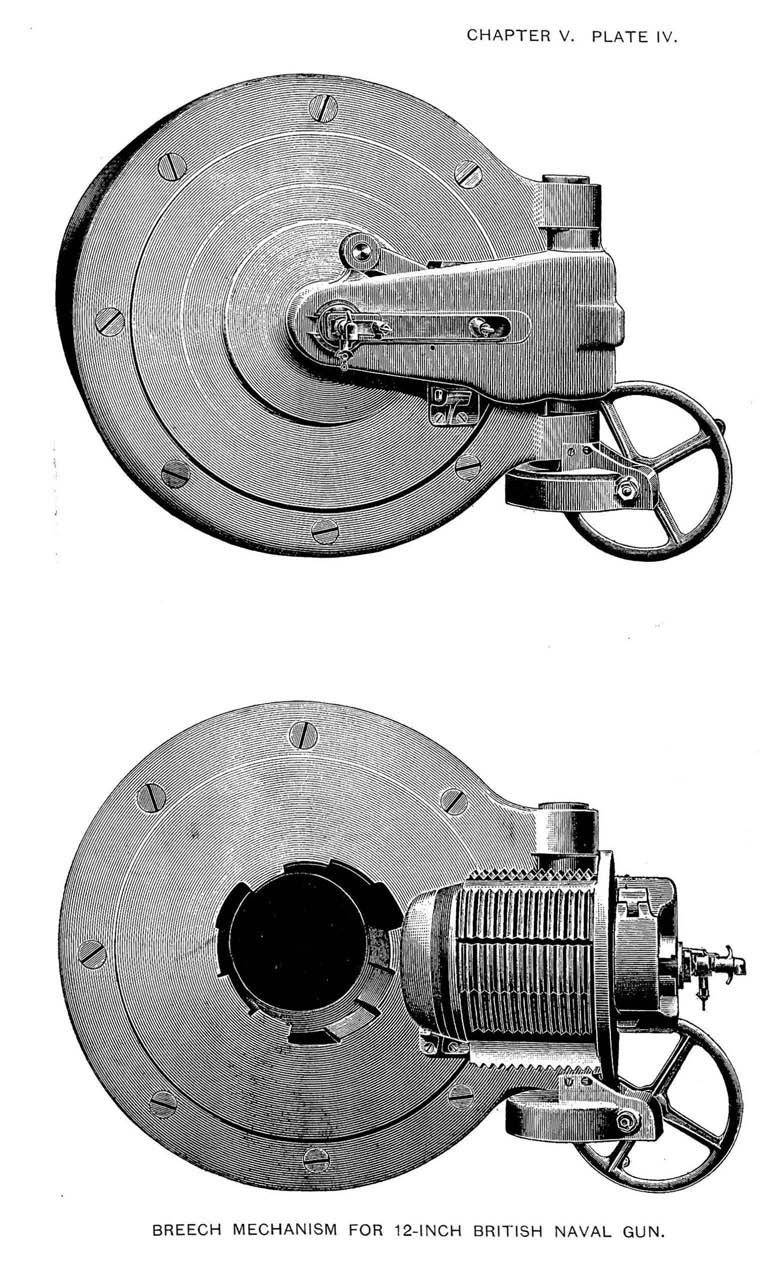
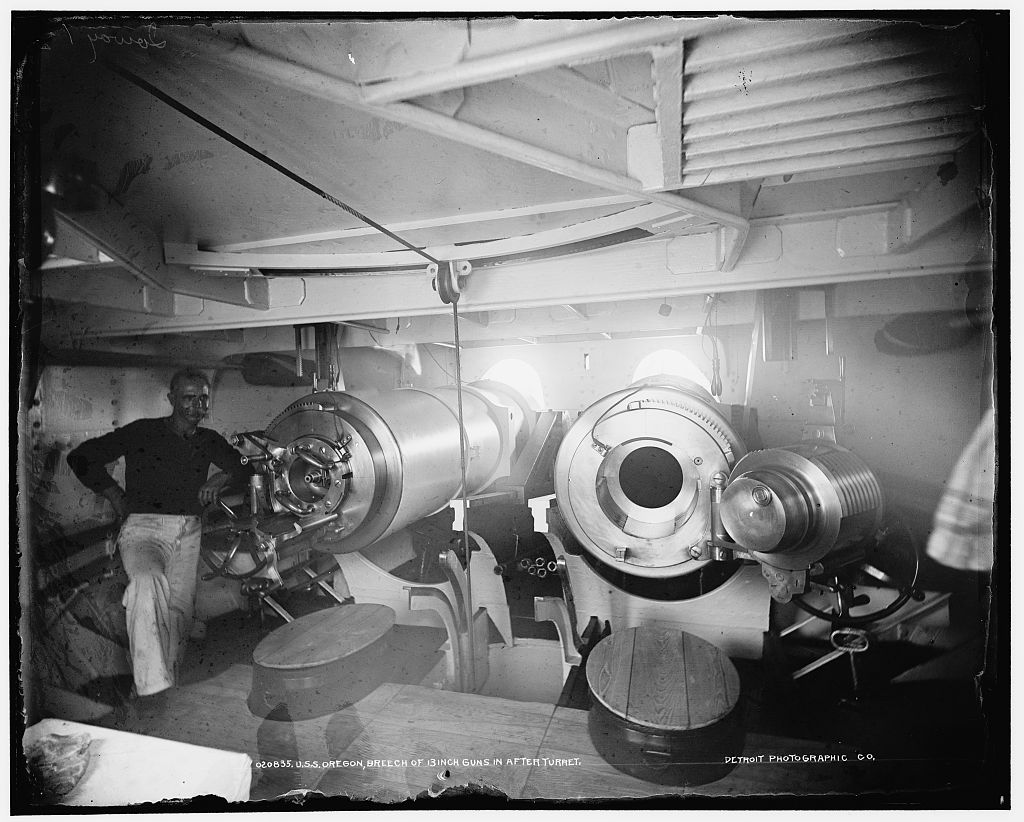
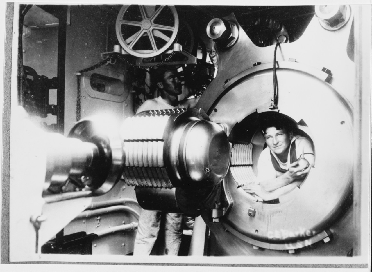
Breech Mechanism - The entire system at the rear of the gun which closes the bore against the force of the firing charge. For large weapons, such as a battleship's main guns, these were usually of an interrupted or stepped screw design, both of which give a very strong seal. For rapid fire and automatic guns that use cartridge cases, a sliding breech-block design is commonly used. These may open and close automatically as the gun is fired.
Breech Block or Breech Plug - The portion of the Breech Mechanism
that actually seals the breech of the gun.
Four-Motion Breech - Early interrupted screw breech design
invented by the French where all of the threads were at the same level.
Usually there were five or six threaded sections separated by equal width
non-threaded sections. This allowed the block to make only a partial turn
before it could be withdrawn from the breech. These breech blocks were
comparatively long as half of the threads were cut away to allow withdrawal,
thus reducing their capacity to withstand the firing stresses. The
mechanism for this type of breech required that the block be first
withdrawn straight back from the gun barrel before it could be moved out
of the way of the reloading process and some had to be disconnected entirely
from the gun. Closing the breech was a complicated operation, involving four
motions: Position the breech block such that the screw could enter the
breech; slide the breech block forward so as to seat it; turn the screw
through part of a turn until the threads meshed with those in the breech;
and finally, lock the mechanism.
Three-Motion Breech - Similar to a Four-Motion Breech, except
that the breech was withdrawn onto a hinged carrier ring. This meant that
the motions were reduced to unscrewing the breech block, withdrawing the
breech block onto the carrier and then swinging the carrier with the block
out of the way of the loading process.
Bofors Ogival Breech - The original design was a three motion
interrupted-thread breech block in the shape of a truncated cone. A later
version was a stepped-thread breech block also in the shape of a truncated
cone.
Welin Stepped-Thread Breech - A breech design developed during the
1890s and named after the inventor, Axel Welin, a Swedish Ammunition Engineer
then residing in London. A Welin breech block usually has three series of
three or four stepped threaded levels and a bottom level which is non-threaded.
This means that a Welin breech block has only one third or one quarter of the
threads removed. The result is that a shorter screw length can be used to obtain
the same strength as a four-motion breech mechanism. Unlike the three- and
four-motion breeches, a Welin breech allows the breech block to be simply
unscrewed a partial turn and then swung out of the way, it does not have to be
withdrawn straight back from the gun barrel before being swung. This design was
so successful that variations of the Welin Breech design were used on most bag
ammunition guns of the twentieth century.
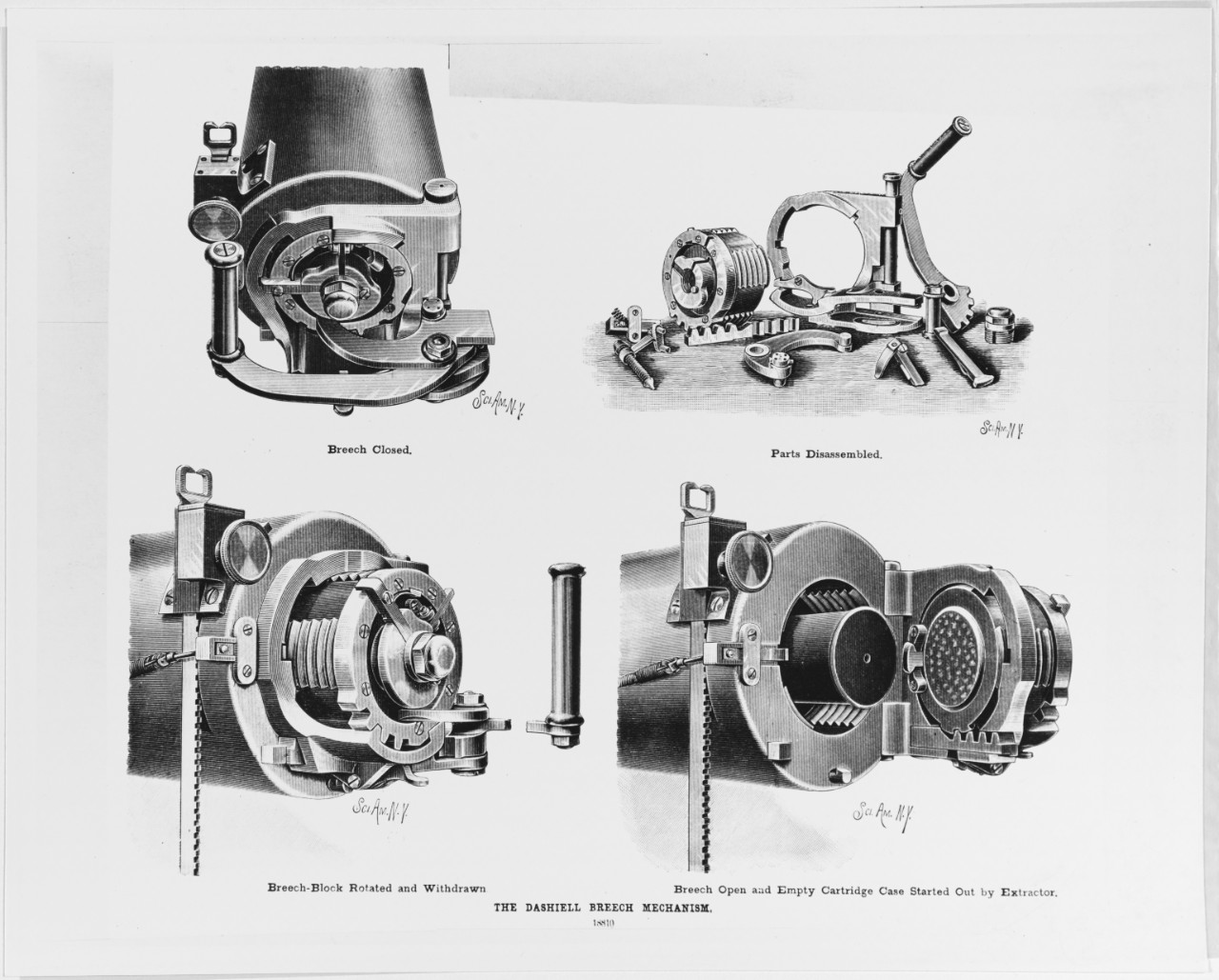
Dashiell Breech Mechanism - Named after its inventor, Lt. Robert.
B. Dashiell, USN, this was an interrupted screw breech mechanism designed around
1890 and its distinctive features were in the method of operating the breech plug
and in the extractor. A single lever was used to unscrew and unlatch the plug. The
plug was supported when withdrawn from the screw box in a combined collar and
tray, hinged to the gun and was provided with an automatic tray latch. All of
the operating mechanisms were carried on the tray casting, except for the trigger,
which was on the gun itself. The key element of the design was the mounting of a
double hinge with cogs to reduce the motions necessary to work the plug.
Farçot Breech Mechanism - Based upon a French invention for
steam and hydraulic applications, this was a three-motion interrupted-thread
system used by France and USA on large-caliber guns of the 1890s. In the Farcot
system, a worm shaft and gearing operated by a crank handle rotated the breech plug
to unlock it from the breech. The plug was then manually pulled straight back onto
a carrier tray to which it latched. The tray was then unlocked from the breech face
and swung clear for loading the gun.
Fletcher Breech Mechanism - Named after its inventor, Lt. Frank Fletcher,
USN, this was a simpler and stronger interrupted screw breech mechanism invented in
the late 1890s that replaced the Dashiell and early Farcot mechanisms in the USN.
In many respects this was an "Improved Farcot" system and is sometimes known by that
name. The main design concept of the Fletcher system was that a worm-wheel on a
vertical spindle worked in a rack on the breech plug and first caused the plug to turn
and disengage the threads and then transition clear of the breech and onto a carrier
tray. The vertical spindle was driven by a crank-driven worm and worm wheel in the
larger calibers and by a simple handle pivoting on the spindle itself in the smaller
caliber guns. On the larger caliber guns, once the breech block was withdrawn,
continued rotation of the crank handle then unlocked the tray from the breech and
swung it clear for loading the gun. The Fletcher system was later modified to work on
Welin breeches prior to the invention of the Smith-Asbury breech mechanism (see below).
Vickers-Maxim Breech Mechanism - An early British type of Welin breech
mechanism. This used a large handwheel attached to gearing used to rotate and
withdraw the breech plug.
Holmstrom Breech Mechanism - A type of Welin breech mechanism for British
bag guns whereby the breech plug was operated by a crank that moved parallel to the
rear face of the plug. Named after the inventor, Carl Holmström.
Breech Mechanism, Pure-Couple - British Welin Breeches of the early 1900s that
used a long, manually operated lever to operate the breech plug. A "couple" consists of
two parallel forces that are opposite in direction and do not share a line of action.
A couple does not produce any translational movement, only rotation. A "pure couple"
always consists of two forces that are equal in magnitude. So, a "pure couple breech
mechanism" is one that uses and produces rotational force in order to work the breech
block.
Smith-Asbury Breech Mechanism - Introduced in 1916 and named after its
inventors, LCDR George Leonard Smith, USN and Draftsman Dorsey Frost Asbury, both
of the Naval Gun Factory at the Washington Navy Yard. This mechanism used gearing to
fully open a Welin breech plug by linking the unscrewing, withdrawing and swinging clear
movements into one continuous action. As can be seen in the photograph below, the start
of the breech threads are undercut at the hinge side to provide clearance for the plug
to swing into position.
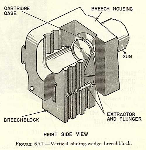
Breech Block, Vertical Sliding-Wedge
- Used on many cartridge guns, this sort of breech mechanism slides vertically
in grooves cut in the housing. After the cartridge is inserted, the
breech block slides up with the sloping part of the forward face wedging
the cartridge home in the chamber. An extractor mechanism catches
the cartridge case rim as the breechblock drops after firing, pulling the
expended cartridge case out of the gun. A few guns use a similar
design, but with the breechblock sliding horizontally. These, of
course, are known as "Horizontally Sliding-Wedge" breechblocks. Vertical
sliding-wedge breech blocks were used on almost all cartridge (fixed, separate
or semi-fixed) gun designs of the twentieth century.
Breech Block, Hotchkiss - A vertically
sliding wedge used on Hotchkiss rapid fire guns of the 1, 3 and 6-pdr calibers
built in the late 1800s.
Breech Block, Driggs-Schroeder -
In this system, the breech block drops to clear its upper end from the
housing of the breech and then revolves to the rear about a horizontal
axis. Used in a few of the small-caliber "pounder" guns of the late
19th century.
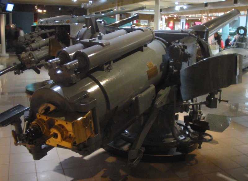
AB - Armstrong Broadside. Inclined ramp type mounting used for British 6" (15.2 cm) guns of the 1880s.
ACAD - Automatique Contre-Avions Double. French for "Automatic AA Twin Mounting."
B - British designation for "Barbette" which at one time was used to denote a turret mounting.
Balanced Turret - Most turreted gun mountings of the 19th century were "unbalanced," that is, the center of rotation was not the same as the center of mass. Thus, when they were trained abeam, they induced a list on the ship, some so badly that the gun muzzles actually went into the water when the ship rolled in even moderate seas. By about the 1890s, "balanced" designs began to be introduced which did have the center of mass and rotation at the same or nearly the same point.
Barbette - The fixed armored ring around the trunk of the mounting. This usually extends from the gunhouse down to the armored or protective deck.
Base Ring - US designation. The entire gun mounting turns on a bearing race which for larger guns is big enough such that there is a space in the center where ammunition can be fed to the gun. For example, all of the fully enclosed single and twin mounts and most of the open single mountings for the 5"/38 (12.7 cm) were base ring types. Mountings for some smaller caliber guns developed during World War II, such as the quad 40 mm Bofors, were base ring types as this type of design distributed the weight of the gun and mounting better than did a pedestal type.
BD - Between Decks. British designation for gun mountings that extended down into the ship while the guns themselves were above the deck. Before World War I, all British Capital ships had secondary guns that mounted directly on the weather deck with nothing piercing that deck down into the ship below. In the 1930s, new gun mounts were developed where the bulk of the mounting was below the weather deck. The term "BD" was used to distinguish this sort of mounting from the previous ones. See "UD" below.
Blast Bags, Bloomers or Gun Bucklers - Canvas, rubber or neoprene covers around the barrel of a gun where it enters the gun port. Gun ports by their nature represent holes in the glacis plate of a turret. When the guns are fired, these holes can allow overpressure or "blast" to enter the the turret, which can disrupt the operation of the turret and injure the gun crew. These holes may also permit water to enter the mounting. The use of blast bags over the gun ports provide some measure of protection from these hazards. Also see "Gun Port Shield" below.
Bogie or Shell Bogie - A wheeled device for moving projectiles around a gun mounting, usually moving on rails. A typical application was for moving projectiles from the fixed portion of the ship onto the rotating turret stalk.
BSG - Bettungschiess-Gerüst. German for "platform firing framework." These were mountings for large caliber guns used as coastal artillery and resembled a railway mounting without the rail bogies. They were supported on a concrete platform by a central pivot and ball race with a roller or bogie at the rear running on a circular arc.
CAD - Contre-Avions Double. French for "AA Twin Mounting."
CADAM - Cadence Améliorée. French for "improved firing." A program for French guns such as the 100 mm/55 Model 1968 intended to increase their firing rate.
CAQ - Contre-Avions Quadruple. French for "AA Quad Mounting."
Carriage - That part of the mounting which is carried in or upon the stand into which the trunnions seat. The carriage moves with the gun in train, but is fixed in elevation with the gun pivoting upon its trunnions for elevation changes.
CAS - Contre-Avions Simple. French for "AA Single Mounting."
Casemate - An armored enclosure containing a gun mounting. Unlike a turret, this enclosure does not rotate.
CP - Centre Pivot. British designation for a gun mounting that has a central axis for rotation on the horizontal axis. These mountings generally used a circular mounting plate bolted to the deck and supported by a below-deck, ring-shaped bulkhead known as the "gun support," which was used mainly for stowage. A lower roller path was machined on the base ring, with a similar upper roller path machined on the bottom of the turntable platform. Between the two machine paths were a ring of horizontal rollers which carried the weight of the mounting and gun. At the center of the turntable was a light cage which contained the vertical thrust rollers. This was the actual "center pivot" point. Electric cabling containing the fire control and illumination circuits ran through the center pivot. This cabling had enough slack to allow the mounting to train to its limit stops. In the USN, this type of mounting was called a "Pedestal" - see below.
Central Pivot - In the USN, this was a compact gun mounting with the center of rotation just below the gun barrel. Used a short "U" shaped bracket whose arms held the trunnions while the base of the "U" was mounted atop a small-diameter turntable.
Delay coil - When guns are mounted closely together in a multi-gun turret, then when the guns are all fired at the same instant, their shells may strike each other in flight or the individual airflow of one projectile may disrupt the adjacent projectiles, causing obvious problems. Starting in the 1920s, the USN alleviated this problem on their three-gun and triple mountings by installing a device which caused a brief delay, about 0.060 seconds, between when the outer guns fired and when the inner gun fired. Another method of reducing shell interference was used by the British in their "Town" and "Colony" six-inch (15.2 cm) cruisers of World War II, where the center gun of each triple turret was set back 30 inches (76.2 cm) from the outer two guns. This allowed all three guns to be fired simultaneously, at the cost of some complications in the design and construction of the gun house.
DCA - Défense Contre Avions. French for "Defense against aircraft" or anti-aircraft weapon.
Dopp MPL - Doppelt Mittel-Pivot-Lafette. German for "Twin central pivot mounting."
DrhL - Drehscheiben-Lafette. German for "turntable mounting." Generally used for turret mountings.
Drh Tr - Drehturm. Another German abbreviation for "Turret."
Elevation - The angle to which a gun can be moved on the vertical axis past the horizontal. For instance, a gun with a 90 degree elevation would be pointing straight up. A gun at 0 degree elevation would be pointing at the horizon. A gun with -10 degree elevation would be pointing below the horizon.
Gunhouse - The armored portion of the rotating structure extending above the barbette.
Gun Port Shield - Curved armor plate attached to a gun barrel such that it seals the gun port in the glacis plate, regardless of the elevation of the gun. Gun ports are by their very nature weak points in the armor protection of a gun mounting or turret. Gun shields seal these openings and are intended to provide at least some measure of protection from shell splinters. In addition, many gun shields are designed so as to keep water and weather out of the interior of the mounting or turret. Some images of gun shields may be seen in these photographs of a USN 6"/47DP and a German 38 cm SK C/34.
Handling Room - Compartment just below the gun mounting where ammunition brought up from lower storage locations is loaded into hoists or scuttles for transferring up to the guns.
Kenyon Doors - British shell-handling device replacing shell bogies in some large-caliber mountings designs of the early 1900s. This was a tilting door which provided a flash-tight means of transferring shells between the shell room and the turret stalk, essentially similar to what the USN called a "scuttle" in their mountings. Named after the inventor, Thomas Kenyon. See this image of the Japanese Battlecruiser Kongô from Vickers Photographic Archive for a photograph of a Kenyon Door as used on that ship.
Kst.Drh.L - Küsten-Drehscheiben-Lafette. German for "coastal turntable (turret) mounting."
LRCS - Low Radar Cross-Section. A mounting that is designed to minimize the radar return, thus making it more difficult to detect.
Magazine
1) For smaller weapons, this is a metal
or plastic box which contains multiple rounds. This is attached to
the weapon and supplies rounds into the firing chamber.
2) Compartment on a ship where ammunition
is stored.
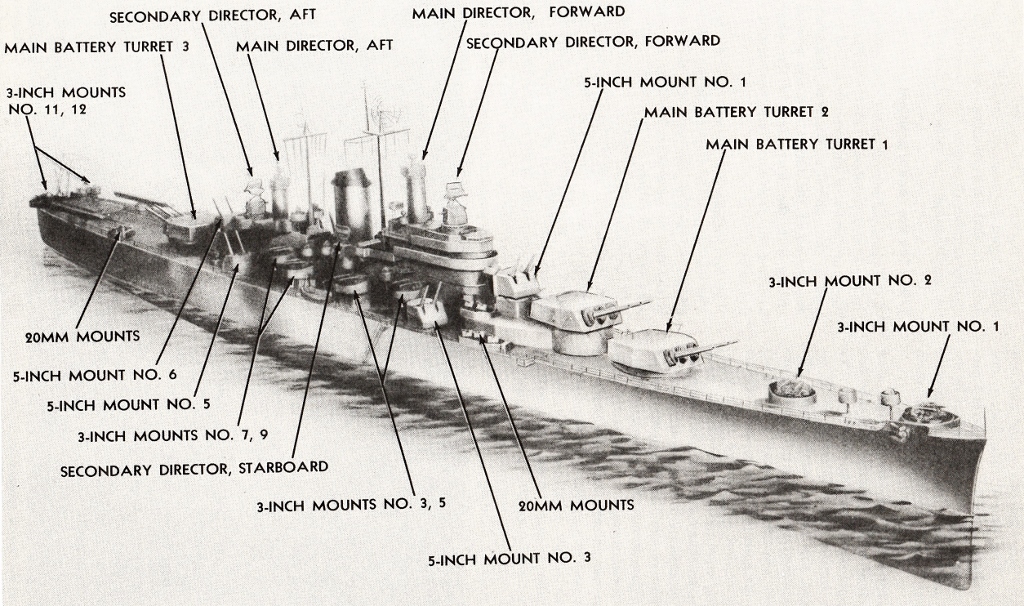
Mounting Numbers, USN - Mountings with guns less than 6-inches (15.2 cm) are usually given a two-digit or three-digit number with the first digit representing the gun caliber and the second and third digits representing its position on the ship. Mounting numbers started at the bow, with even numbers to port and odd numbers to starboard. For example, for the Des Moines class (CA-134) cruiser pictured at right, the 5-inch (12.7 cm) mountings were numbered 51 for the bow, 52 and 54 were on the port side, 53 and 55 were on the starboard side, and 56 was at the stern. The 3-inch (7.62 cm) mountings started with 31 on the bow and ended with 312 for the port stern mounting. These mounting numbers such as "52" were usually pronounced as "five-two" rather than as "fifty-two." Larger caliber mountings were usually the Main Battery Turrets and were numbered sequentially starting at the bow such as "Turret 1" and "Turret 2" as shown here.
MPL - Mittel-Pivot-Lafette. German for "central pivot mounting."
P - Pedestal. British designation for a compact gun mounting with the center of rotation just below the gun barrel. A short "U" shaped bracket held the trunnions with the base of the "U" mounted atop a small-diameter turntable. Similar in design to a Central Pivot mounting as used in the USN.
Passing Box - A small container mounted between compartments with a flap or door on each end and used to provide a flash-tight method of moving powder bags from one compartment to another. Usually there is a mechanical connection such that only one flap can be open at a time.
Pedestal - In the USN, this is a mounting where the entire gun carriage turns on a roller-race. The carriage is usually slab-sided with the sides running all the way down to a platform whose bottom forms the top of the roller race.
Pintle - A flexible mounting where the gun is mounted at the top of a vertical post or rod.
Powder Room - A compartment where propellant charges are stored.
Projectile or Shell Flat - Usually refers to that portion of a magazine directly adjacent to the rotating structure of a turret. May also be used to refer to that portion of the rotating structure onto which projectiles are moved from their storage locations in the magazines.
Recoil Cylinders and Counter-Recoil Cylinders - Recoil Cylinders absorb the forces generated when the gun is fired. These normally consist of a hydraulic system using a piston whose rod is surrounded by a spiral spring. The cylinders are normally secured to a stationary part of the mount while the piston rods are secured to the gun. When the gun fires, the piston moves through the cylinder and the recoil force is checked by the friction of the hydraulic fluid as it passes from one side of the piston to other side via apertures not filled by the piston, such as grooves in the wall of the cylinder. By varying the width of these grooves, the amount of friction generated as the piston moves can be increased or decreased as desired. During the recoil stroke, the spiral spring is compressed. This compression force is used to push the gun back into battery. As the piston returns to its starting point, the hydraulic fluid again moves through the apertures, aiding in controlling the counter-recoil stroke. The counter-recoil stroke can be violent and in larger guns counter-recoil cylinders are used to better control the speed of the return stroke. A counter-recoil cylinder is essentially a recoil cylinder designed so as to produce the most friction as the gun returns to battery.
RP - Remote Power. World War II British designation for gun mounts equipped with RPC. Usually followed by a number which represented the type of power control. The RP10 series were hydraulically operated while the RP50 series were electrically operated.
RPC - Remote Power Control. Also known as "Auto Control" in the USN. This is a subject in itself. In its barest essentials, this means that the gun director and associated components automatically control the laying of the guns without manual intervention by the gun crew.
Scuttle - In the USN, a shell or powder handling device that allows a flash-tight transfer from one compartment to another, such as from a handling room up to a gunhouse. Commonly, this was a handle-operated rotating hollow drum with an opening on one side, with the opening accessible from only one compartment at a time. For example, a scuttle going between a handling room and a gunhouse would be loaded on the handling room side with a powder bag. Moving the handle rotated the opening in the drum over to the gunhouse on the other side, thus keeping the two compartments isolated from one another. At right is a picture of a scuttle used to transfer powder bags from a magazine onto a powder hoist on USS Iowa BB-61.
Sighting port - An opening for a gun-sight in the front of the gun-shield or turret glacis plate.
Sighting hood - Armored cover protecting the gun-sights protruding through the roof of a gunhouse or turret, although many of these were completely open to the front. On British capital ships of the World War I-era, superfiring turrets could not fire within 30 degrees of the axis because the blast effects would have penetrated into the lower turrets via the front openings in the sighting hoods. These hoods also represented a weak point in the protection of the turret and acted as shell traps. Several ships were damaged during World War I when German shells hit these ports, perhaps most notably on Q turret of HMS Tiger during the Battle of Jutland (Skagerrak) in 1915.
Shell Ring - On USN battleships and cruisers built in the 1930s-40s most of the projectiles were stored on fixed and rotating rings which were part of the upper and lower shell flats. Each storage flat was sub-divided into three concentric rings. The outer, or fixed ring, is attached to the stool and does not rotate. The center ring, or shell-handling platform, is part of the rotating structure including the gunhouse and contains the projectile hoists. It also mounts the parbuckling gear for moving the projectiles from their storage locations and onto the hoists. No projectiles are stored on this ring. The inner, or rotating ring, is a power driven platform resting on rollers which can be rotated in either direction and is supported by the rotating structure. The inner ring may be locked to the rotating structure (center ring) or to the stool as needed. Normally, the shells on this ring are the ones fed to the guns while those on the outer ring are moved only during non-firing periods.
Short Trunk / Long Trunk - British definitions. Short Trunk refers to a turret mounting which has its shell rooms and magazines on the same level. Long Trunk refers to a mounting where the shell rooms and magazines are on different levels. Having these spaces on different levels means that the turret stalk will be longer, hence the name.
Sleeving - In a multi-gun turret, if each individual gun can be raised independently of the other guns, then the guns are said to be individually sleeved. Guns that are not individually sleeved are said to share a "cradle" (UK usage) or a "slide" (USA usage). See "Turret Definitions," below.
Stabilized mounting - A type of mounting which keeps the weapon at a constant point of aim regardless of the movement of the ship. May use as many as four different axes of motion; elevation, train, crosswise tilt (roll correction) and lateral tilt (pitch correction).
Stalk - That portion of the rotating structure of a turret that extends down into the ship.
Stand - That part of the mounting which is secured to the structure of the ship and in or upon which the carriage rests and is moved in train.
Stool - The fixed circular foundation bulkhead that supports the rotating elements of the gun house.
Superfiring - A gun mounted such that it can fire overtop another mounting without elevating its gun barrels from the horizontal is said to be superfiring. For example, on most ships with two forward turrets mounted on the centerline, the second turret from the bow is mounted higher than the first turret such that it may fire forward at almost any elevation. The second turret is thus superfiring.
Swashplate Engine - This was a type of steam-powered reciprocating engine employed by the British that used a circular plate (swashplate) in place of a crankshaft. These swashplate engines contained multiple pistons which were used to press down in sequence near the outer edge of the plate, making it wobble as it rotated about its center. Using a swashplate engine for turret training and elevation had the advantage of smoother incremental movements, as the jerking caused by the back and forth motion of the pistons was not directly coupled to the driveshaft.
Train - The angle to which a gun or turret can be rotated on the horizontal axis. For instance, a bow gun or turret pointing directly forward is said to be trained to 0 degrees. If it could rotate to point directly astern, then it would be trained to 180 degrees.
Transferable Mounting - A British term used in the early part of the twentieth century, meaning that the gun mounting was simply bolted to the deck with no other connections and so could be easily removed and used elsewhere. Replaced by "UD" (see below) in most official publications.
Turret vs. Mount - There is often a minor controversy about whether a particular rotating enclosed gun emplacement should be called a "Turret" or a "Mount." In the USN, the difference between a turret and a mount is that a "Turret" is built into the ship, has a stalk that extends well below the weather deck and includes a barbette, while a "Mount" is not part of the ship's structure and does not include a barbette. As a general rule, USN 5 inch (12.7 cm) and smaller guns are in "Mounts" while 6 inch (15.2 cm) and larger guns are in "Turrets." Other navies had similar distinctions.
Turret Definitions - In the USN, when multi-gun turrets are described as "two-gun" or "three-gun" it means that their guns are individually sleeved and that each gun can elevate independently of the others. When the mounting is described as "twin" or "triple" it means that all guns share a single slide or cradle and that individual guns can not elevate independently from the others. Other nations do not use these distinctions. On my weapon pages, the description for each weapon will indicate whether the mountings were individually sleeved or not.
UD - Upper Deck. British designation of the 1930s and 1940s referring to a gun-mounting that did not pierce the deck on which it was mounted. See "Transferable Mounting" and "BD," above.
VB and VCP - Vavasseur Barbette and Vavasseur Central Pivot Mountings. British gun mountings of the late 1800s that used inclined ramps to help absorb recoil forces. Named after Joseph Vavasseur (1834 - 1908) who at one point was connected with the Armstrong-Whitworth Co. and who is best remembered for inventing the process of using hydraulic pressure to fit copper driving bands onto projectiles in 1874 and the first pivot mount with hydraulic recoil brakes in 1881.
25 August 2008 - Benchmark
30 January 2009 - Updated British Nomenclature, added definition for Holmstrom breech mechanism
05 November 2009 - Added French mounting designations
17 September 2010 - Added more French designations
16 April 2013 - Minor changes to the Japanese and United States gun designation descriptions
11 July 2014 - Additional definitions for breech mechanisms
28 July 2014 - Changed links to other Gun Data datapages, added to liner description
22 November 2014 - Minor changes in gun nomenclature section for clarity
16 May 2015 - Added liner nomenclature for USN weapons and additional information about Joseph Vavasseur
24 October 2015 - Minor changes and additions in gun nomenclature section
02 December 2015 - Changed Vickers Photographic Archive links to point at Wayback Archive
24 March 2016 - Added information to USA Designations
03 May 2016 - Converted to HTML 5 format
03 March 2017 - Added Short / Long Trunk definition
13 July 2017 - Updated links
25 July 2017 - Added USN Mounting Number definition
01 December 2017 - Added information on Japanese head stamp dates
06 December 2017 - Minor changes
26 February 2018 - Added akan, SAK, TAK and ubätsautomatkanon definitions
15 July 2018 - Added "centimeters" nomenclature to France Designations
28 March 2019 - Noted switch by France to OTO-Melara 76 mm gun
19 April 2019 - Added link to French Ammunition, Guns and Mountings definitions
30 September 2019 - Minor changes for clarity to Japan Designations
26 October 2019 - Added Bofors designation in Britain / UK Designations section
26 November 2019 - Additional information for French designations regarding caliber designations
07 March 2021 - Minor formatting changes
21 May 2021 - Added "Salvo Latch" definition
01 July 2021 - Added "LRCS" definition
19 August 2021 - Added Ogival breech mechanism definition and added to Japanese Mounting designations
08 October 2021 - Added "ATB" definition
17 November 2021 - Moved Gun Pit definition to Miscellaneous Definitions and added data to British designations
08 April 2022 - Added link
25 August 2022 - Added to slide definition
03 February 2023 - Added definitions for Chase, Housing and Neck
17 May 2023 - Minor change for clarity
25 June 2023 - Added information and photographs for screw-type breech mechanisms
30 August 2023 - Minor change for clarity to slide and slide cylinder definitions and added conical liner to liner definitions
09 December 2023 - Minor changes for clarity to monobloc construction
09 March 2024 - Added information in the USA designation section for the serial number of replacement guns
23 November 2024 - Added definition for Key and added to Slide cylinder definition

